Linear Optical Systems

Phase Aberrations
Phase Aberrations - Geometrical view
- Wavefront departs from flatness
- When focused, rays do not intersect at the same location
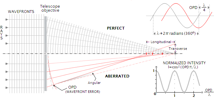
Phase Aberrations - Fourier Optics view
- Now, , thus the PSF departs from the simple square modulus of the aperture, as presented in previous lectures.
- This yields asymmetry and spread, and a loss of angular resolution as well as:
- a loss of Strehl ratio
- further attenuation of spatial frequencies in the OTF

Seidel Aberrations
Seidel Aberrations


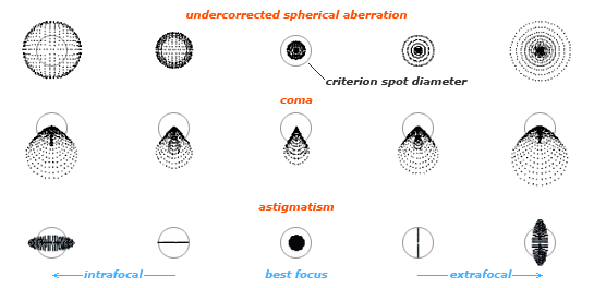
- Primary aberrations from optical system misalignment or
manufacturing error - Seidel aberrations for monochromatic light:
- Spherical aberration
- Coma
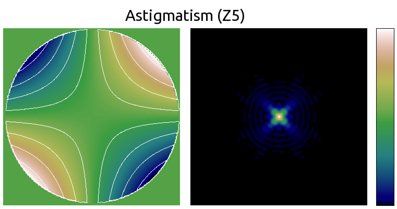
- Astigmatism
- Curvature of field
- Distortion
- Chromatic
(Not phase aberrations as described previously in this lecture, i.e. for a single point like object. Those are field dependent or wavelength dependant aberrations)

Seidel aberrations: Coma
- Also a field aberration in many optical system (i.e. something you get when looking off-axis)

- "field Aberration": an aberration that varies as a function of position in the output field (field = image plane)
- Characterised by core + tail

Seidel aberrations: Spherical
- Often due to polishing error

- The Hubble space telescope is an infamous example

Seidel aberrations
| Geometrical (ray) view | Fourier optics view |
|---|---|
 |
   |
Beyond Seidel: real eye cases

Zernike polynomials to describe phase aberrations
Zernike polynomials/modes

Zernike polynomials: background
- The mathematical functions were originally described by Fritz Zernike in 1934.
- They were developed to describe the diffracted wavefront in phase contrast imaging.
- Zernike won the 1953 Nobel Prize in Physics for developing Phase Contrast Microscopy.
Zernike polynomials/modes

Why Zernikes?
- Zernike
 polynomials have nice mathematical properties:
- They are orthogonal over the continuous unit circle:
- All their derivatives are continuous.
- They efficiently represent common errors (e.g. coma, spherical aberration) seen in optics.
- They form a complete set, meaning that they can represent arbitrarily complex continuous surfaces given enough terms.
Zernike polynomials

Zernike polynomials...

... and corresponding PSFs


Zernike polynomials to describe phase aberrations
Phase expansion and phase variance
The phase can be described as a superposition (sum) of Zernike polynomials
where the coefficients are calculated as follow:
The phase variance is then readily computed as:
Impact on Optical Transfer Function


Aberration retrieval


- Using Wavefront sensors

- Hartmann, Shack-Hartmann sensor
- Foucault knife, pyramid sensor
- Interferometer: Michelson, Mach-Zehnder, Fizeau,…
- Self referenced interferometers: Shearing, point diffraction,…
- Using the image itself
- Phase diversity

Wavefront Sensors
Linear Optical Systems

Wavefront Sensors (WFS)
- A device that is measuring the wavefront phase (and potentially amplitude)
- Many wavefront sensors measure the phase first derivative (local slope) or second derivative (local curvature), some use a mix of both
- First derivative wavefront sensors:
- Shack-Hartmann
- Shearing interferometers (lateral, radial, rotation)
- Pyramid, Foucault knife
- First derivative wavefront sensors:
- Second derivative wavefront sensors:
- Curvature
- And then some device measure the phase difference with some reference wave:
- Point diffraction interferometer, Michelson, …
- But all do that through an intensity measurement of some sort
Shack-Hartmann Wavefront Sensor: how does it work?
Shack-Hartmann WFS

Shack-Hartmann WFS

Shack-Hartmann WFS

Shack-Hartmann WFS

Shack-Hartmann WFS

Shack-Hartmann WFS

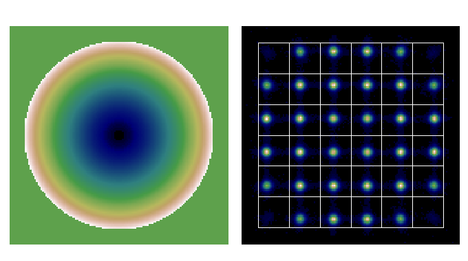
SHWFS Extension in two dimensions
Shack-Hartmann in 2D

- A Shack-Hartmann sensor measure the average X and Y gradient over the subaperture
Shack-Hartmann in 2D

Shack-Hartmann in 2D

Shack-Hartmann in 2D
Shack-Hartmann in 2D

Shack-Hartmann in 2D

Shack-Hartmann in 2D

Shack-Hartmann in 2D

Real-World Considerations
What WFS to choose?
- Noise, usage of light
- Dynamical range
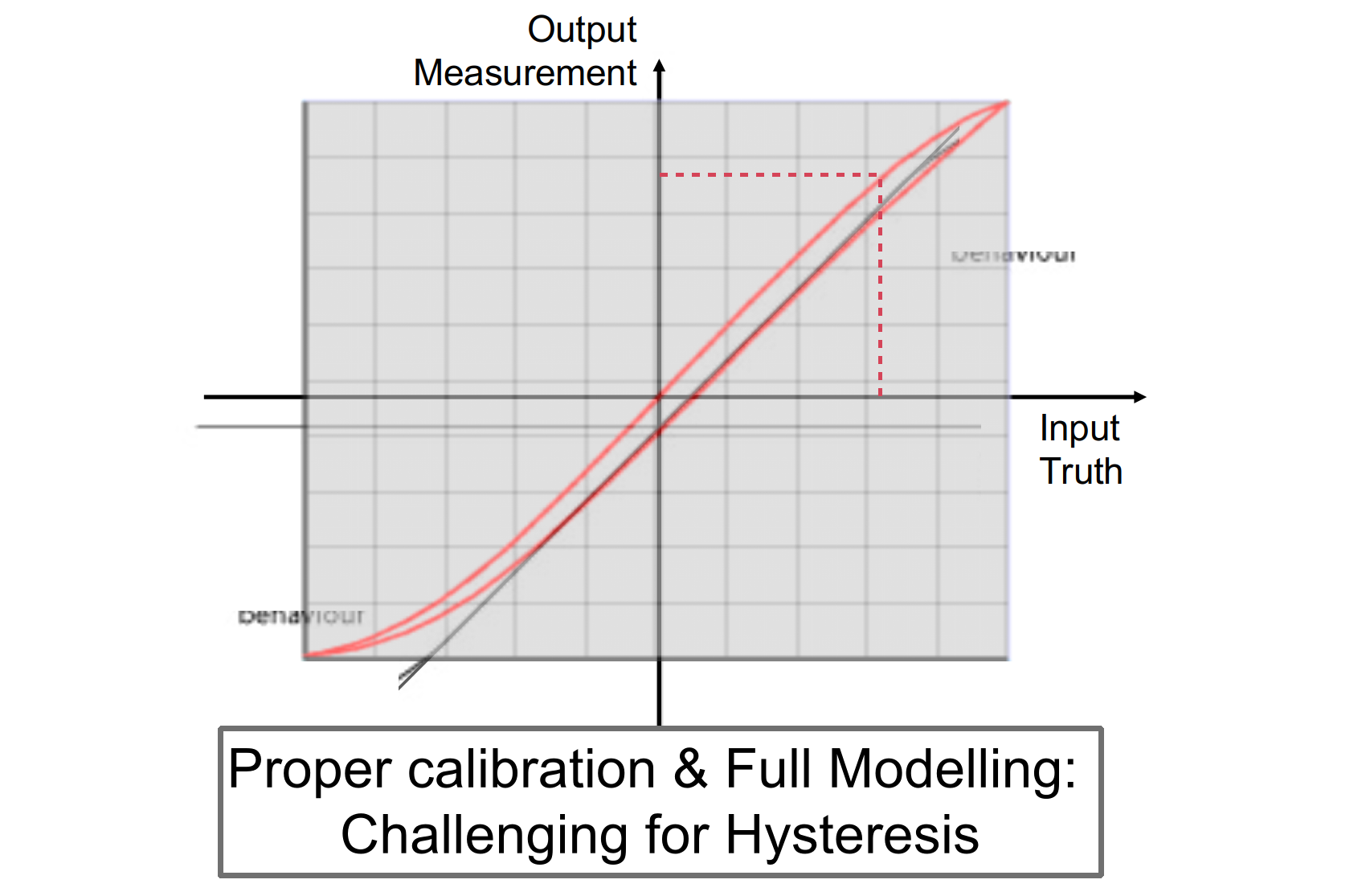
- Linearity, hysteresis
- Cost
- Polychromaticity
- Spatial aliasing
- Speed, computational requirements
- Solution uniqueness
- Extended sources
- Self referenced
- Ease of implementation
Sensor Transfer function

Sensing issues: non linearity

Sensing issues: Calibration error

Sensing issue: Hysteresis
Noise and SNR
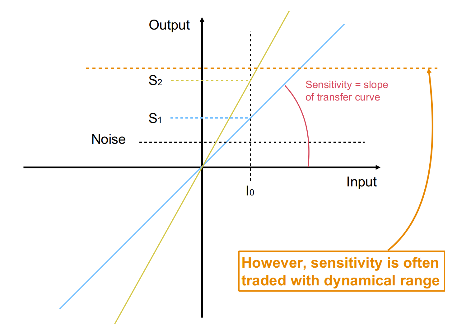
Trade-offs and choice drivers

Other Real-World Considerations
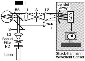
Practical implementation
| In Astronomy | In Ophthalmology |
|---|---|
 |
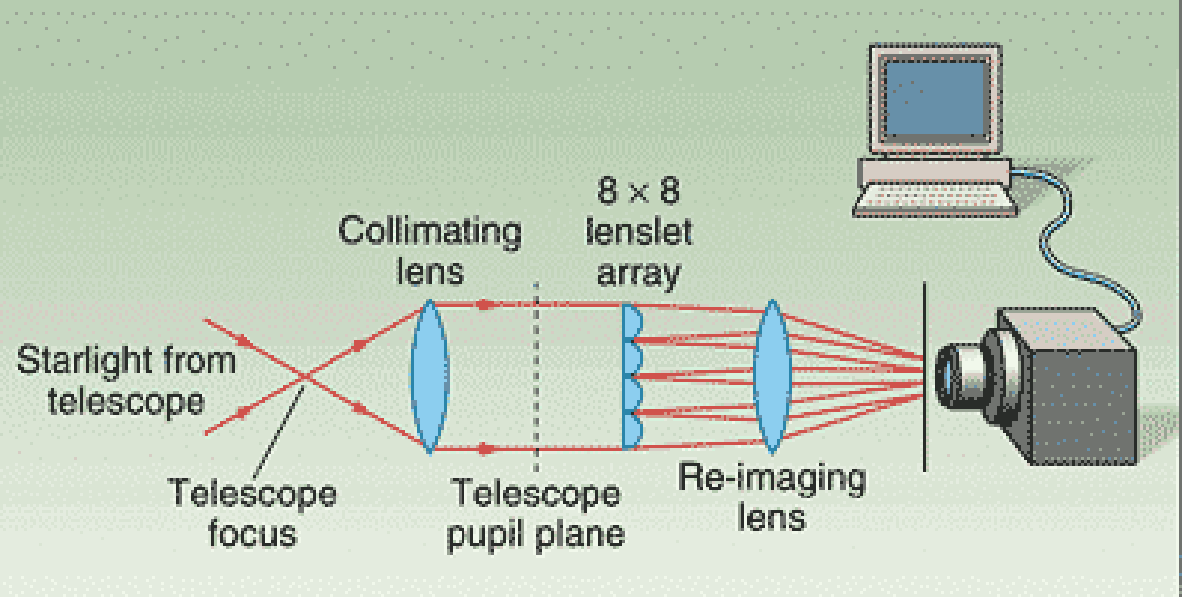 |
- Field stop
- Collimating optics (usually lenslet 1F behind collimator)
- Lenslet array (most commercial arrays have pitch of 100-1000 μm)
- 2D Sensor: Most CCDs/CMOS have pixels of 2 (CMOS for phones) to 20 microns (CCDs for science applications). Typical format to .
Applications & Needs

Alternatives WFS techniques
Alternative: Phase diversity
- Focal plane method

- Acquire an "in focus" image
- but (wavefront) phase is lost during the image formation
- ...and an image with some added phase "diversity", e.g. focus
- The second image lift the sign uncertainty
- Then use a minimisation package (Steepest descent, Conjugate Gradient, Levenberg–Marquardt, etc) to find the phase that reproduce best the images, or AI.
Minimisation & Fitting
- The problem: Given data points at , find model parameters so that the least square distance model-data is minimum:

- Iterative methods
- Steepest descent, Conjugate Gradient,
Levenberg–Marquardt - Issue with local minima:
